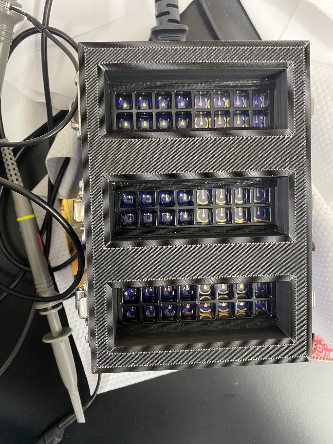
Intro
ADOpt came from a practical bottleneck in the lab. Biosensor deposition involved too many manual steps, too much setup time, and bench equipment that was not shaped for the workflow. The project asked a narrower question: can one reliable signal, delivered in the right physical format, save researchers time and increase throughput?
This was my first substantial hardware project. It went through many iterations, taught me how much mechanical integration matters, and eventually produced two modules that were sent to Grenada for field testing.
Purpose
The goal was not to build a general-purpose function generator. The goal was to make one specific deposition signal well, package it into a compact module, and make it easy for another researcher to use.
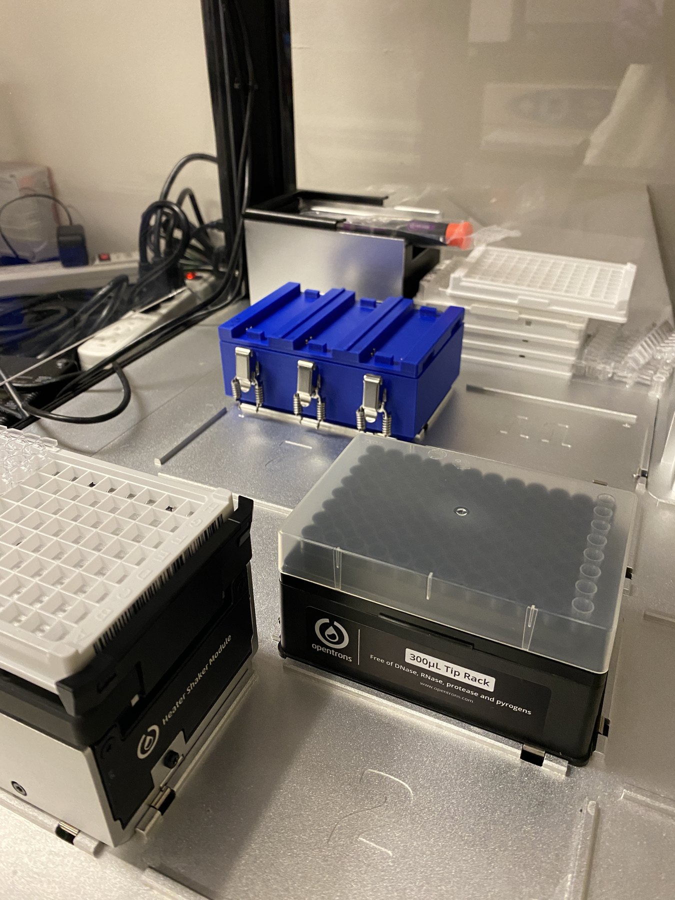
ADOpt was designed around an Opentrons-compatible workflow, though in practice it was often used as a benchtop device. That still mattered: the geometry, cabling, manifold access, and chip contact strategy were all shaped by the automation workflow around it.
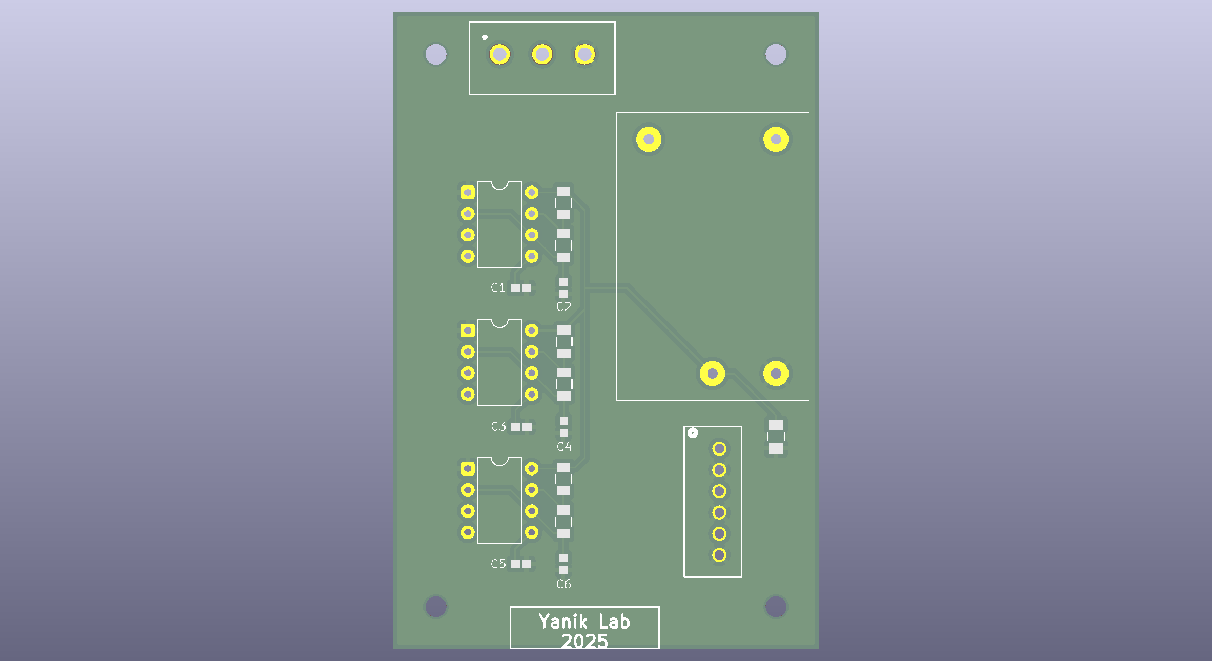
- 555-timer signal-generation circuit
- 50 Hz, 10 Vpp square-wave target
- PCB designed in KiCad
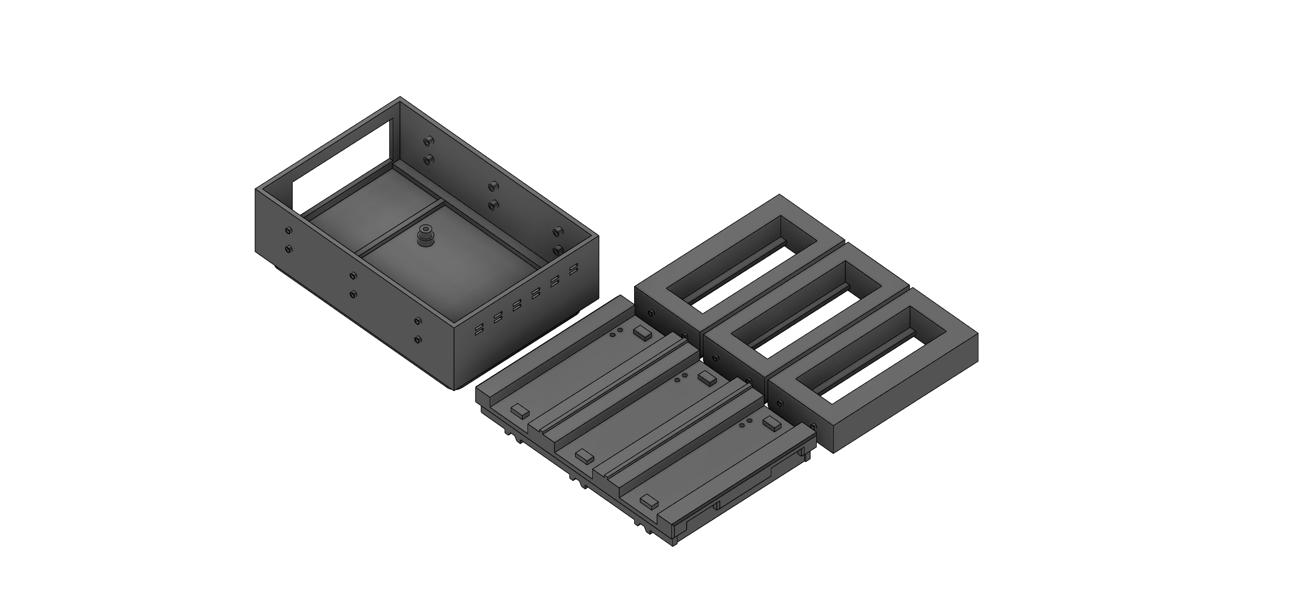
- CAD enclosure and pressure fixtures
- Pogo-pin, copper-tape, and spring-contact delivery experiments
- Fluorescent and magnetic bead deposition workflow
- Two modules shipped to Grenada
Implementation
The electrical design generated a repeatable deposition waveform. The mechanical design made that waveform usable: chips had to sit under micro assay manifolds, seals had to hold pressure, contacts had to route from single-sided Ti/Au chips, and the workflow had to stay understandable in the lab.
The original chip-contact method used copper tape to route the working and counter electrode contacts from the bottom of a glass slide to the top. Pogo pins then touched those routed contacts. Later designs explored spring contacts and overhead pogo-pin approaches to reduce manual prep.
Design decisions
| Decision | Selected direction | Why it fit the lab workflow | Tradeoff / next step |
|---|
| Signal source | 555-timer circuit | Simple, compact, repeatable, and dedicated to one deposition signal | Not a flexible lab function generator |
| Output target | 50 Hz, about 10 Vpp square wave | Matched the deposition condition the workflow needed | Tune only around the useful operating region |
| Contact strategy | Copper routing, pogo pins, spring-contact tests | Kept the glass-chip geometry usable without redesigning the chip | Manual contact prep should be reduced |
| Mechanical pressure | Manifold clamp, then three-block fixture | Directly addressed gasket sealing and workflow repeatability | Pressure fixture still needs serviceability polish |
| Deployment style | Benchtop first, Opentrons-compatible geometry | Let the tool work in the real lab while preserving automation compatibility | Full robotic integration can come after reliability |
Validation
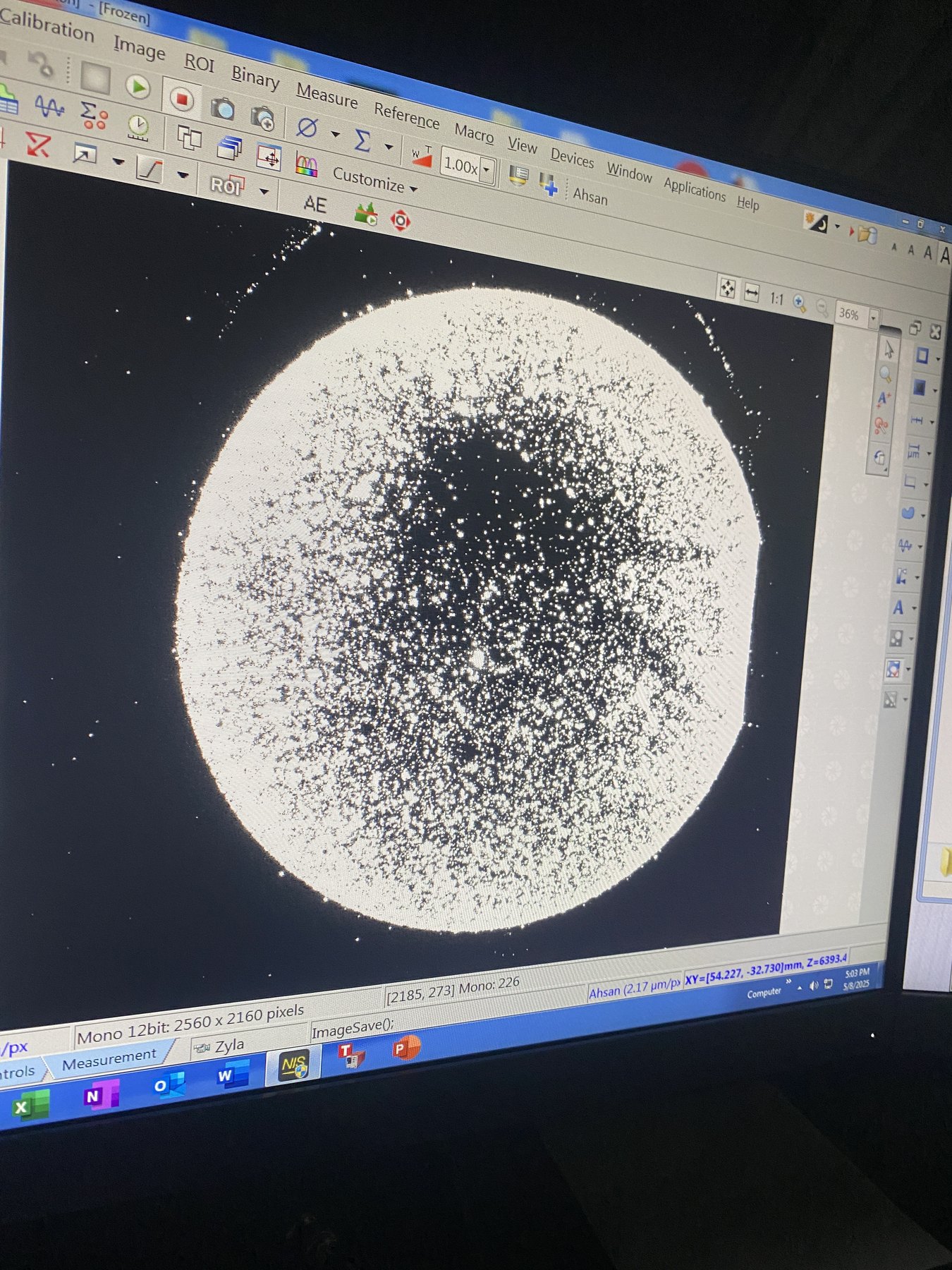
The module was validated electrically with an oscilloscope and experimentally through bead deposition. In testing, the ADOpt signal produced brighter fluorescent bead outputs than the Rigol benchtop generator being used previously. The likely explanation was that the purpose-built signal had characteristics better suited to the deposition process than the broader spectrum or behavior of the bench generator.
The optical validation used microscope imaging with fluorescence. Testing included molar concentration ranges around 10^-4 M to 10^-7 M, with many chips prepared, labeled, imaged, and reviewed.
The linked schematic and use-procedure table show the handoff trail behind the tool: electrical behavior, use steps, and the practical details needed by another researcher.
Lessons from deployment
The Grenada-deployed fixture revealed a mechanical issue. The one-piece pressure structure could let the side compartments prop up the center, preventing enough force from sealing the middle manifold. The workaround was to run two manifolds at a time. The later design split the fixture into three independent pressure blocks so each manifold and gasket could seal properly.
That lesson is the heart of the project: the circuit can work and still fail the workflow if the physical interface is not right.
Results
- Built a compact signal-delivery module for a specific deposition waveform
- Replaced a benchtop generator in the deposition workflow
- Supported Opentrons-compatible lab automation constraints
- Shipped two units for Grenada field testing
- Produced useful optical deposition results and informed later SDU work
Future work
- Standardize assembly and use documentation
- Reduce manual chip contact preparation
- Improve serviceability for field deployments
- Carry the contact, manifold, and pressure lessons into the Sensor Deposition Unit